Use the arrow keys to navigate the article.
Type /main to leave the article
Type /link to open the link
This is a project I half-made a few years ago, I intended to return to it but life got in the way as it does.
I forgot it existed until now, I luckily wrote notes for myself.
Despite it being incomplete, there is still alot of merit to the project
I got the idea after seeing a
much more advanced project here : https://github.com/mxgmn/WaveFunctionCollapse.
*Remember to type /link to open the link*
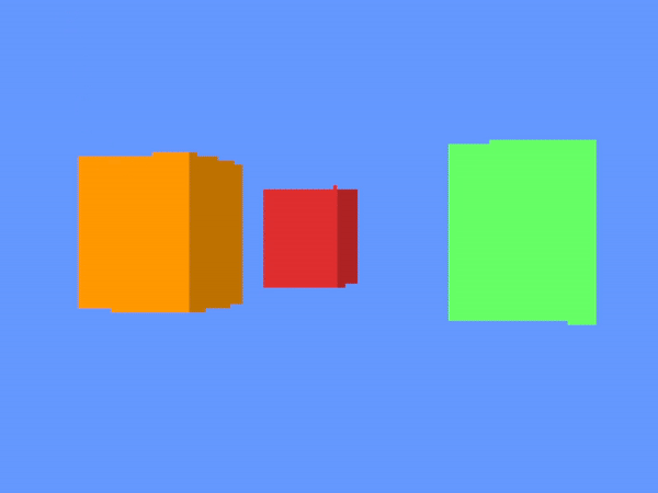
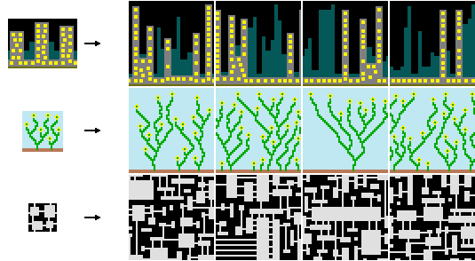
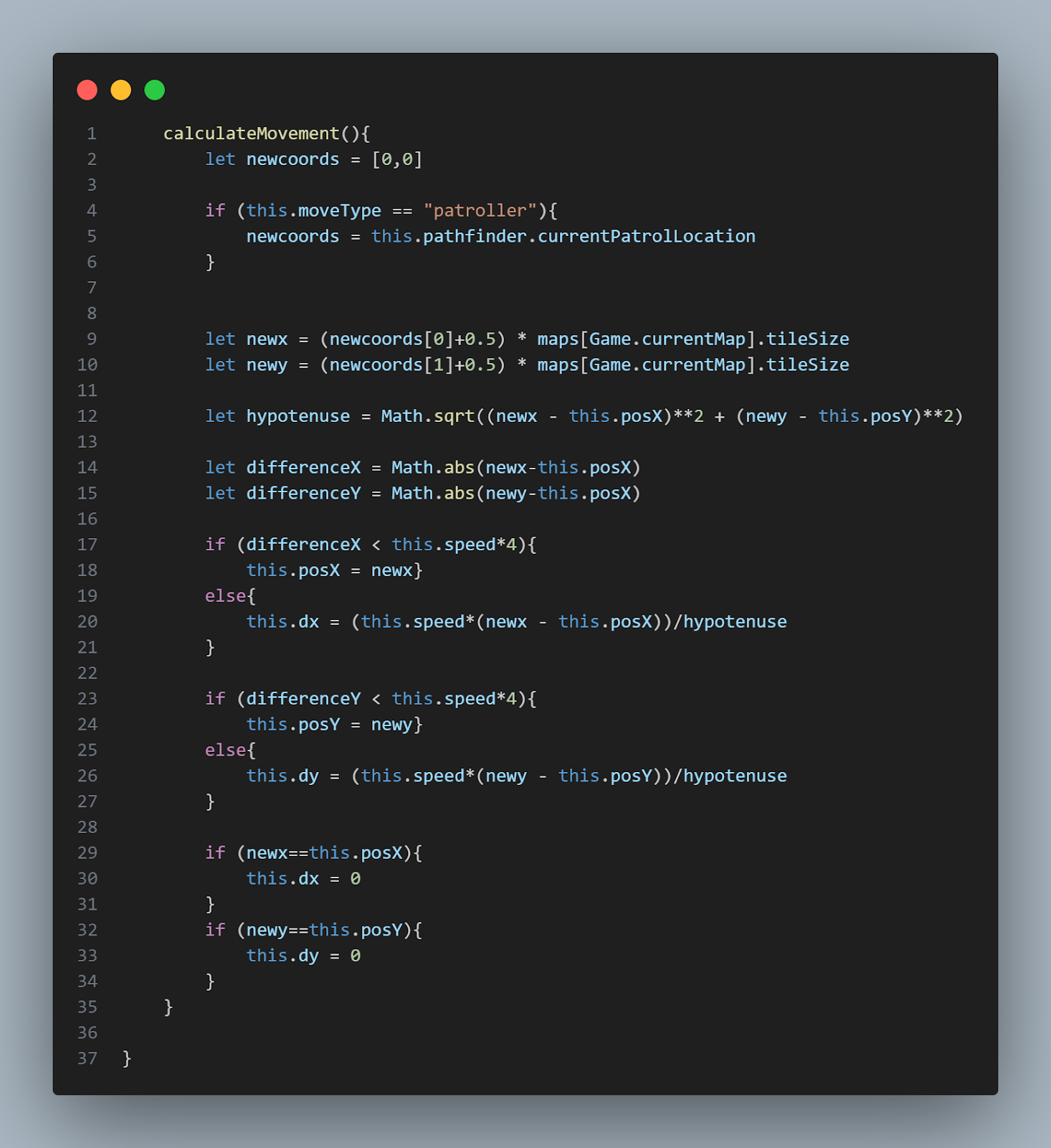
The basic idea is a terrian generator with a few rules:
-The water can only be adjacent to the Sand or itself
-The Sand can be adjacent to Water,Grass or itself
-The Grass can be adjacent to Sand,Forest or itself
-The Forest can only be adjacent to Grass or itself
*It should also be noted that I created this project during Year 12 and
had not yet learnt of tree traversal algorithms*
I went through three iterations or "attempts" at creating the desired
result, none of them fully worked at the time.
FIRST ITERATION
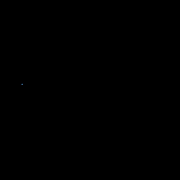
This attempt was very basic, it selected cells at random to "collapse". However this didn't work because it meant there would be
"clashes". For example a forest-empty-water , nothing can fill the empty cell in the middle. In order to get it to work I had to
make Sand a universal cell, this meant it could be placed next to any other cell. It was also very inefficient as it would spend
a long time searching for an uncollapsed cell.

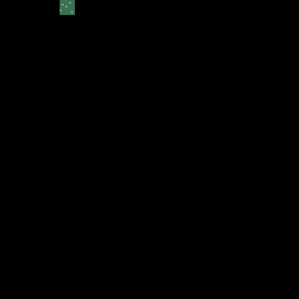
SECOND ITERATION
This one worked similarly to the first attempt, however it would only collapse
empty cells adjacent to already collapsed cells. It would choose these randomly however, so there was still opportunity for
clashes between cells. If I had known what breadth-first search was before I made this, it would have been alot better.
I had to still
use the universal Sand cell to bridge those gaps. This method was more uniformly distributed however as clashes would occur less often and hence Sand
wouldn't fill the grid.
*I trimmed the large video down, as it would be too large as a gif*
THIRD ITERATION
With this one I decided to collapse an empty cell adjacent to the last edited
cell (shown in red). I stored all the last edited cells in a stack and if the branch reached a point that it couldn't further edit,
it would move back down the stack until it found a cell with adjacent empty cells.
Both of the last two methods are obviously
very crude breadth-first search and depth-first search algorithms, however I didn't know this at all :(
However there were still
clashes when the new branch couldn't mix with the old branch.
*As a note, this gif has been sped up, it actually took 3 minutes
to complete the whole grid*
Fin.
Use the arrow keys to navigate the article.
Type /main to leave the article
Type /link to open the link
*Note: This description has been written previously by me, and it is LONG... the html is very bad and I wouldn't read the whole thing if I were you*
The game can be played at https://ordie.itch.io/raycaster-mansion
*use /link to open the link*
Basics
In most common rendering engines, such as webGL, the screen is divided into pixels with coordinates with (0,0) being located in the top left. And the positive y-axis pointing down.
This algorithm (A raycaster) is an algorithm that can convert a 2d array of ‘walls’ to a 3d rendered scene. This is done by shooting out a number of rays from the player. Each ray will then hit a wall. Each ray from left to right is then drawn onto the screen from left to right as a rectangle.
The width of that rectangle being gameWidth/numOfRays.
The height of the rectangle is then determined by the distance the ray travelled before it hit the wall. The further it travelled the shorter the rectangle is.
The rectangles x position is the rays number in the for loop, i, multiplied by the width of each ray. So (i*gameWidth)/numOfRays.
The rectangles y position will be half of the screenHeight minus half of the ray height. So (screenHeight-rectangleHeight)/2.This means that the horizon will lie at the centre line of the screen.
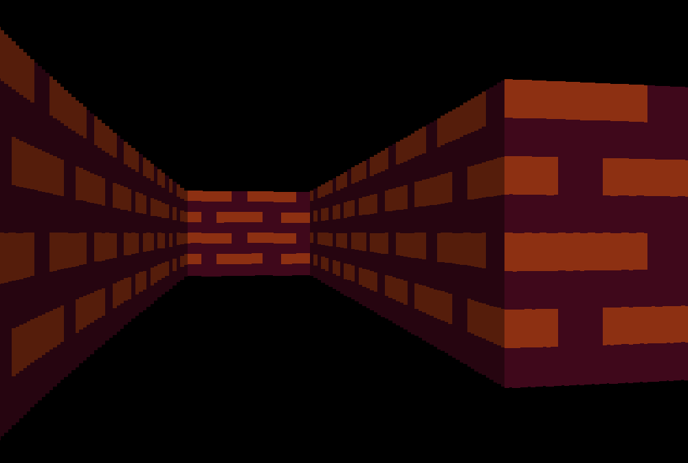
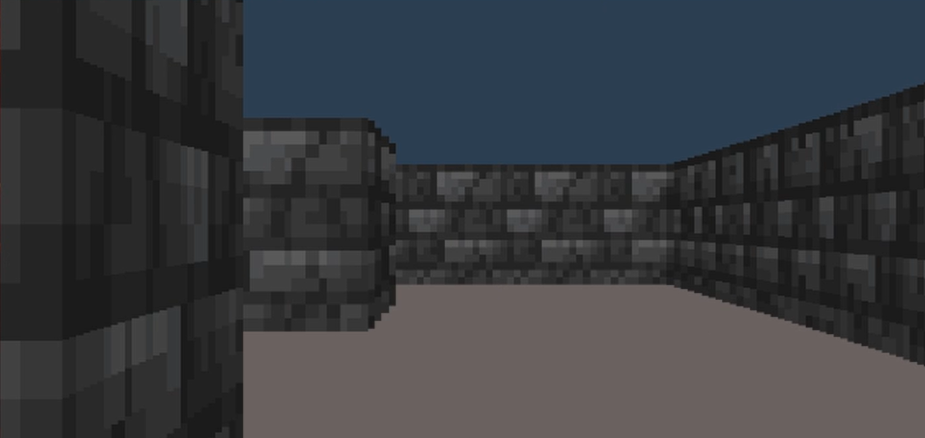
If you do this algorithm you will get a scene that looks like this.
This is the basics of raycasting and I will explain each step in more detail.
Shooting a ray
If we imagine the map being an 8x8 2d array.
map = [[1,1,1,1,1,1,1,1],
[1,0,1,0,0,0,0,1],
[1,0,1,0,0,0,0,1],
[1,0,1,0,0,0,0,1],
[1,0,1,0,0,0,0,1],
[1,0,0,0,0,1,0,1],
[1,0,0,0,0,0,0,1],
[1,1,1,1,1,1,1,1]]
If we know the tilesize, tilesize = 64, (the tilesize actually just represents the tiles width) and the player angle. We can shoot a ray from that player angle and see where it intersects with the wall.
The idea is that you check first the vertical lines and horizontal grid lines, and whichever hit first is the ray position that you’ll use. It does this by hitting each horizontal or vertical grid line and checking if it is a wall. If not you increment the ray to the next grid line.
Horizontal lines
There are 2 main parts to firing a ray.
- Jumping to the first horizontal line
- Finding the X offset that will put it onto each sequential horizontal line
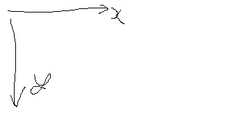
For the first part our problem becomes something like the image. It is easy to find that first rayY because it is simply the startY position of the ray rounded to the nearest line. Finding the first rayX position is harder however. We can construct a triangle between the player position, the first ray location and the nearest point on the horizontal line. 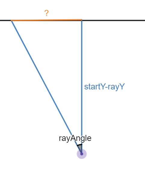
We can see that the problem becomes simple and the initial offsetX:
-1/tan(rayAngle) * (startY-rayY)
If you’re confused about the -1/tan(rayAngle) and why it’s not tan(rayAngle), I explain more about it in the explanation video.
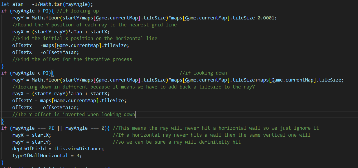
For the next part of shooting the ray we need to iterate with the offset that we found for the X and the tilesize for the Y. We keep doing this until we hit a tile that isn’t air or we reach the max view distance.
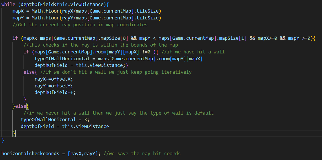
Both of these processes will return a horizontal hit position for a ray at the given angle from the start location. It should be noted that there are lots of edge case checks here and any edge cases will be sorted. This is because if a graphical error occurs it looks very drastic and they are never wanted. Here is an example of one of the graphical errors.
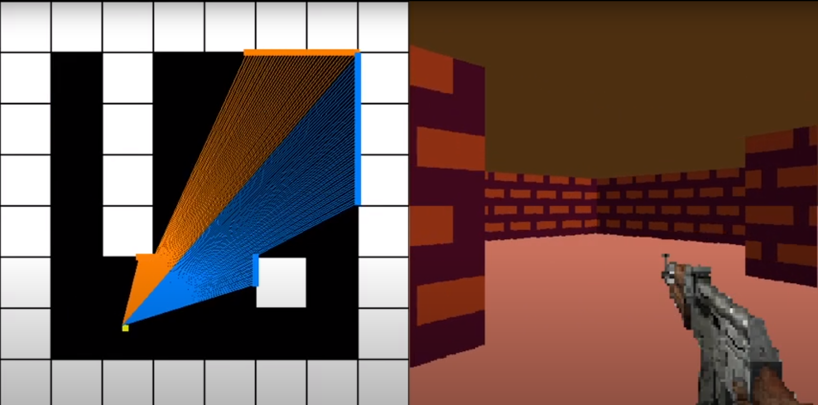
Now we have done horizontal lines and we can tackle vertical lines. Luckily we have done most of the work. The code is almost exactly the same except for the fact that we check if the player is looking left or right and change lots of X’s for Y’s. The same algorithm applies and I will not paste the code because it looks the same. There is a better explanation in the video.
Once we do this process for both horizontal and vertical rays we should get something that is represented by this image. With blue lines meaning the vertical ray hit first and orange lines meaning the horizontal ray hit first.
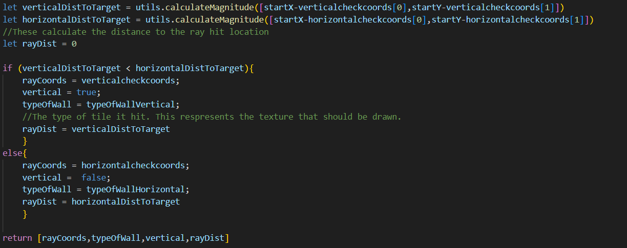
Final ray hit location
The final ray hit location is then determined by which ray hit position is closer to the player.
We check this with a pythagoras’ triangle to find the hypotenuse.
Drawing each rectangle
We need to shoot 1 ray for each degree in the FOV, so an FOV of 60, would shoot 60 rays.
We will create a for loop that goes between 0-60 and increments the ray_angle by 1 degree each time. However this might produce a low resolution result which makes it harder to see the textures. So we can add in a resolution variable which will shoot a resolution amount of rays per degree, for example a resolution of 3 would shoot 3 rays per degree of FOV. Another variable we need is the max ray distance, we find this by doing the square root of the map size to find the corner to corner distance.
maxRayDistance = 8*tilesize
for (let i = 0;i<(fov*resolution);i++){
rayDistance = #What is returned from the ray shooting algorithm
rectWidth = screenWidth/(fov*resolution)
rectHeight = (rayDistance/maxRayDistance) * screenHeight
rectXPos = (i/(fov*resolution)) * screenWidth
rectYPos = (screenHeight/2) - (rectHeight/2)
}
#Then we draw the rectangle
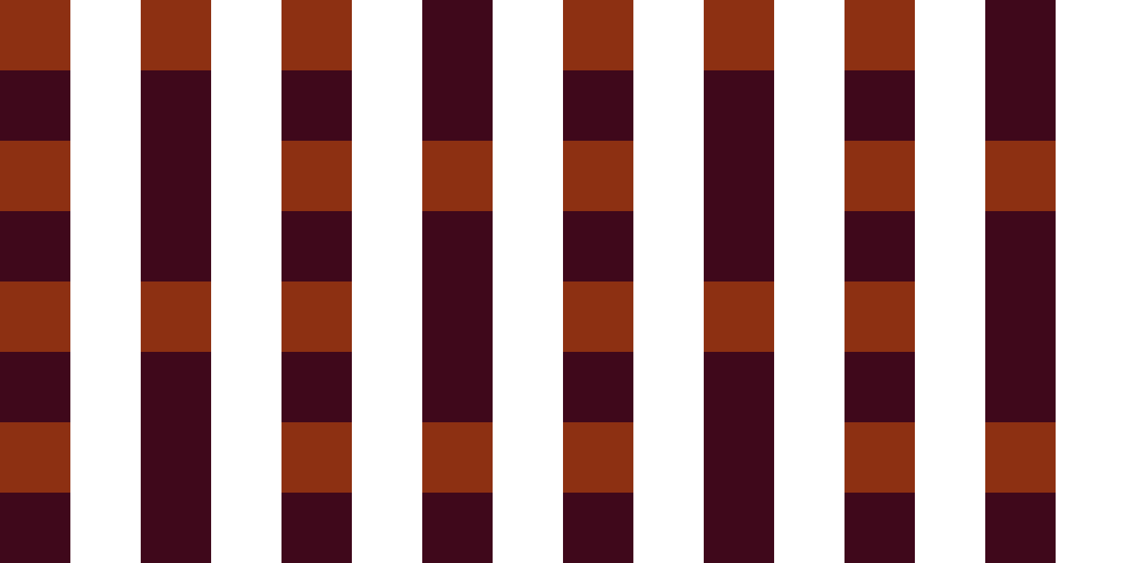
Drawing textures
We can draw textures by simply splitting up a png file into a number of strips and instead of drawing a rectangle we can draw a specific strip of the png file. However we need to determine which texture X coordinate we should use so we know which strip of the png file to use. We can figure this out simply by checking the x (or y coordinate if a vertical wall) of the ray hit location in world space. Then modding this by the texture size. Additionally we can draw vertical walls a slightly darker colour than horizontal walls to give some simple shading.
It should look like this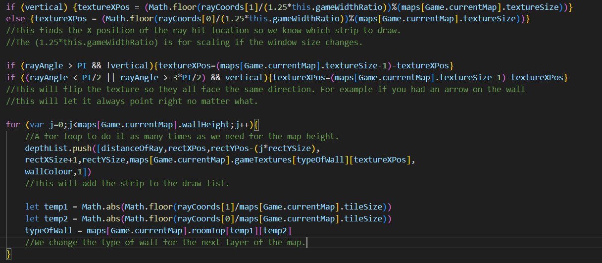
Player Movement
What we need to find is the change in x, dx, and the change in y, dy, each frame based on the angle of the player. Then depending on the inputs we can move the player in the desired direction.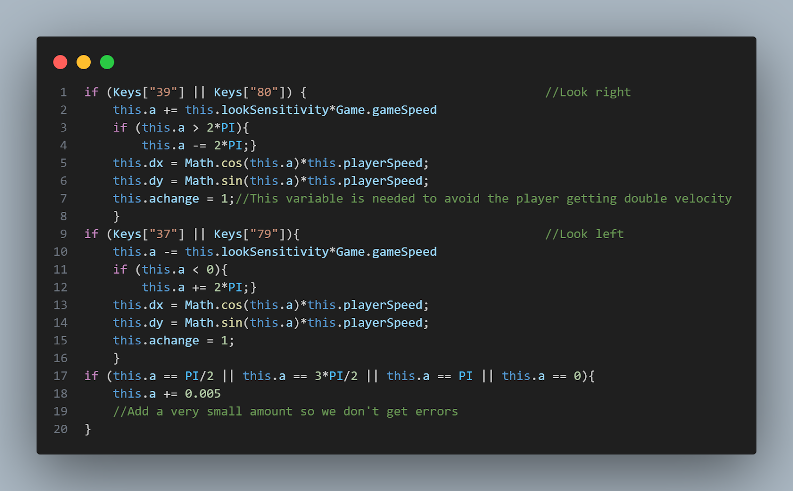
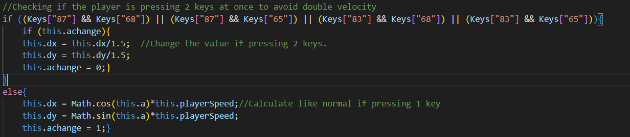
Then we can apply this dx and dy value based on the players inputs, e.g pressing forward means the player position will be incremented by positive dx and positive dy, and backward is negative dx and negative dy. And because moving sideways means moving perpendicularly, we can say the player will move in the dx direction by the dy offset and vice versa.
Additionally I allowed it so the player can look around using O and P as an alternative to using the arrow keys. This is because my client told me that some laptops don’t have arrow keys that are easily pressable and he would prefer if he could use alternative keys.
Checking for collision is very simple, we just take in a position and determine whether that position in the map array is wall. So we just have to check if the item in the array in that position is not a 0.
Object Pooling
With the rendering system pixi.js, there are limitations. If you draw a rectangle, it is created as an object.
#Create a Graphics object, set a fill colour, draw a rectangle
let obj = new PIXI.Graphics();
obj.beginFill(0xff0000);
obj.drawRect(0, 0, 200, 100);
#Add it to the stage to render
app.stage.addChild(obj);
However this doesn’t work as well for game rendering because each rectangle will persist each frame. In practice this will look completely normal frame by frame. But the frame rate will slowly start to decrease over time. This is because each time a new rectangle is being drawn on the screen, a new rectangle object is created. This object will stay in memory and will be drawn again and again each frame. This means the rectangle count just increases over time, bolstering the frame rate.
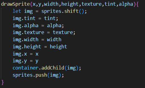
A way around this problem is to reuse the same rectangles over and over, however this created a new problem of how I was going to tackle this. I ended up initialising a queue right at the beginning of the program, with a fixed size matching the number of rectangles I need each frame. This is calculated with resolution*fov. Each item in the queue is a blank rectangle object.
When I need to draw a rectangle I would dequeue an object and then edit its properties.
Then after drawing it to the screen I would enqueue it back. This meant that the objects wouldn’t persist each frame allowing me to fix the frame rate problem.

This is my first working example of object pooling. This was before further optimisations.
Moving entities
The main idea for moving the entities is to have an algorithm deciding their movement in a separate class, then using association with the main enemy class. This means we can switch the movement types in and out whenever we need without creating a whole new enemy class. So the main problem with movement is determining how to move the position at a constant speed from point A to point B (assuming it is a clear straight line path).
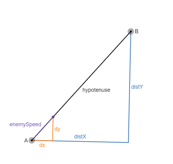
We can see that the dy and dx values create a triangle similar to the main triangle between point A and point B. This means that enemyspeed/hypotenuse is equal to dy/distY (and the same with dx).
dy = (distY * enemySpeed)/hypotenuse
dx = (distX * enemySpeed)/hypotenuse
Then we can move the enemy each frame by dy and dx.
This will give us the code.
It is difficult to show a working example of movement in a photo so I will refer you to the video to see an example of it.
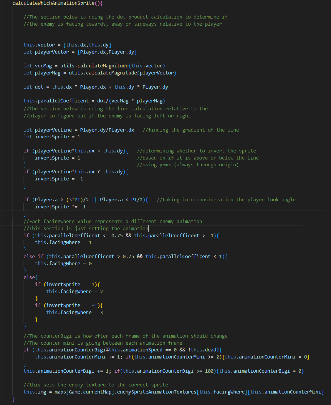
Facing the enemy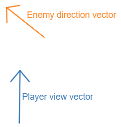
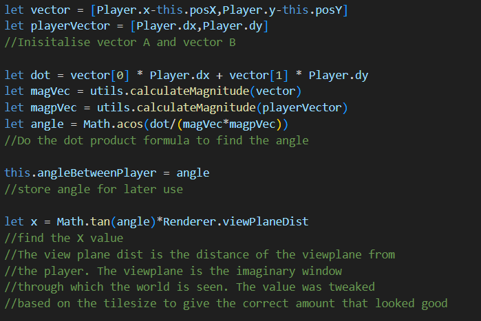
The way entities work in a raycaster means that the sprite is “always facing” the player. The only way we will be able to make it look like the sprite is moving and facing in different directions is by swapping out the sprite. We can figure out each vector in relation to each other.
Both vectors are just their respective dy’s and dx’s.
We can take the dot product of each vector and divide by the product of their magnitudes to find out a number between -1 and 1 depending on how aligned they are.
a · b = |a||b|cosθ
⇒ cosθ = (a · b)/|a||b|
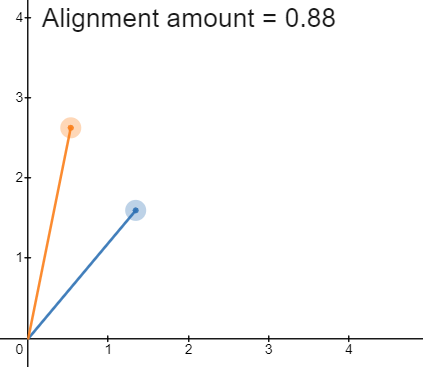
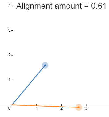
Using this value I decided some bound which would determine whether the cutoff for if the entity was sideways or towards the player. I decided on values being between 0.75 and 1 for moving away, and likewise -0.75 and -1 for towards.
Anything else would be moving sideways. Now we reach a problem with this method. We can't know which way they are moving sideways, whether it's left or right.
For example these two have the same alignment amount despite being on either side of the main player view vector.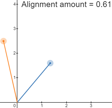
We can find whether the enemy vector is on the left or right by finding the line through the player position vector and determining if the enemy position vector lies above or below that line. 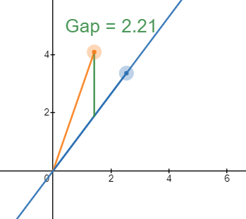
If this gap value is positive then it is on the left side of the player and hence we should play the walk left animation. And if negative we play the walk right animation.
However the positive and negative value changes based on which way the player is facing.
Here is an example in action.
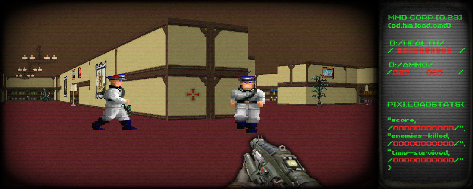
Drawing the ui
The basic idea of the UI is to have a base image which contains the background for the ui.
All the stats and fx can then be layered on top of this.
Using a text object in pixi.js was an option. However it doesn’t give me the full functionality that I require. So I decided to use an image composed of different numbers.
I can then split up this image into an array of textures and each time I need to display a number I index the array and display the correct number.
In order to actually display the correct stats I need to split up the number into 11 sections. So the problem becomes turning an integer into a 11 character long string. This is integer manipulation.
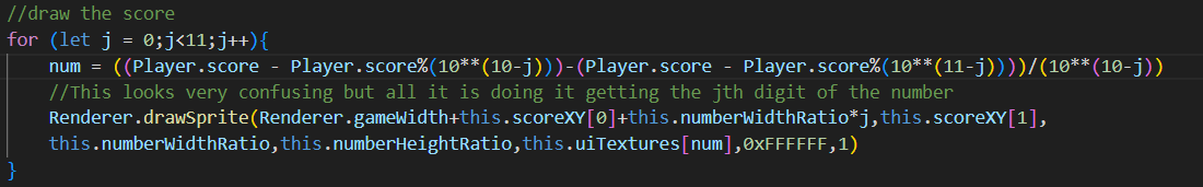
This looks very complicated but it is simply a for loop that isolates each digit of the score number and displays the digit at the correct location. The this.scoreXY attribute decides the initial location to start drawing the score, and each digit of the number is drawn j*numberwidth away from that start location. This algorithm is implemented for all the stats including the ammo except the ammo only goes for 3 digits instead of 11.
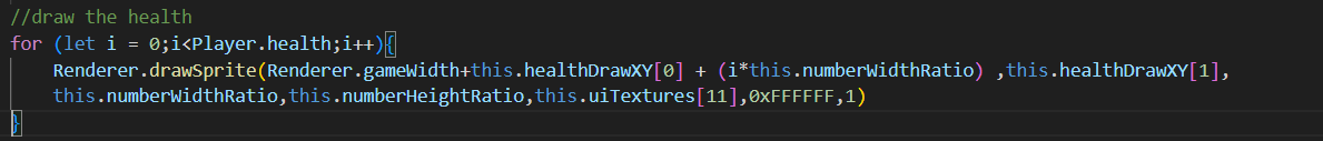
Drawing the health is much more simple as it just draws up until the health the player has, i.e. the for loop goes until Player.Health
Additionally the crosshair, ui scanlines, ui vignette and gun are easy to draw as they are just a single drawSprite call.
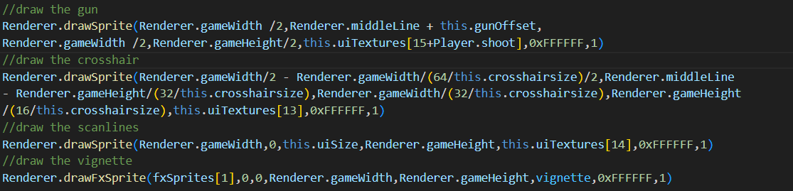
These calls are quite large so I’ll explain each one:
- The first 2 parameters are just setting the x and y position to draw the sprite, it is always drawn at the same X, but the Y will change when reloading, this is controlled by the this.gunOffset. The Renderer.middleLine is just the middle of the screen and changes with screenshake and view bobbing, everything is drawn from this line.
- The next 2 are the fixed size of the sprite.
- The last ones are the actual texture for the sprite, the tint, and the opacity.
- The first 2 are still the same X and Y, the X is fixed but because the window is resizable I’m not able to hardcode the position on the screen, same with the Y position
- The just the size of the sprite, once again I can’t hardcode them
- The last ones are the actual texture for the sprite, the tint, and the opacity.
- These scanlines shouldn’t be mixed up with the main screen scan lines as they are different. Everything else is the similar to before.
- This is using the drawFxSprite call so the vignette can’t be layered up on itself lots of times. But everything else is the same.
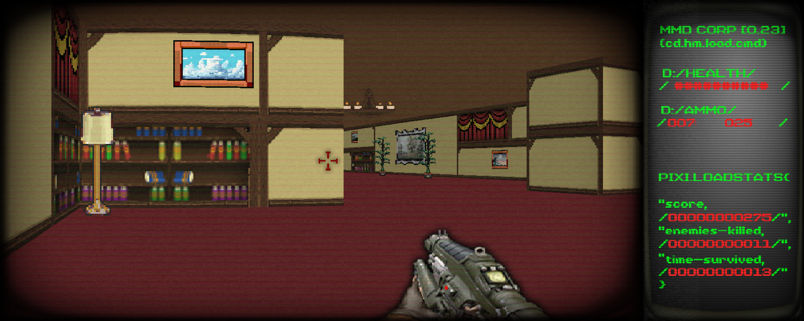
After all that it should look like this.
Drawing entities
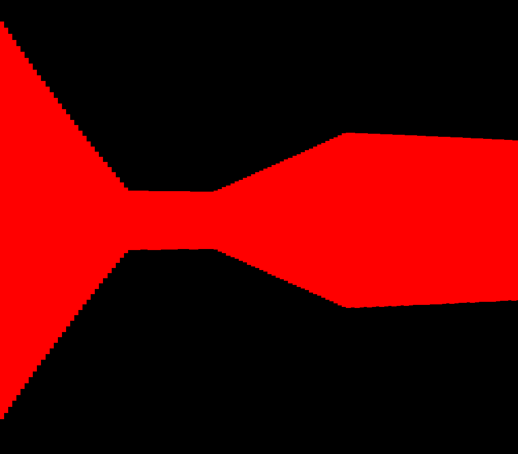
Drawing entities is the most difficult problem in the renderer, hence why I’ve left explaining it to later, it is done separately from the raycasting. We have an entity position in world space. We need to figure out where on the screen we should draw it.
It becomes this problem, where we have to work out the orange Xpos distance. Where the purple dot is the entity and the green one is the player. The red represents the view frustum and fov.
The blue line that is perpendicular to the bisector of the view frustum is the view plane of the object. Hence the y represents the distance along the screens X coordinates we should draw the entities sprite. If we construct 2 position vectors, one between the player and the entity (A) and one for the player's look direction (B), we can find the angle between them using dot product, similar to before. With this angle we can work out the opposite side to it using SOHCAHTOA. This gets us very close to working out how far along the screen we should draw the entity and is the first part of solving it. However because dot product returns absolute values as angles we don’t know whether to draw the entity on the left or right side of the screen.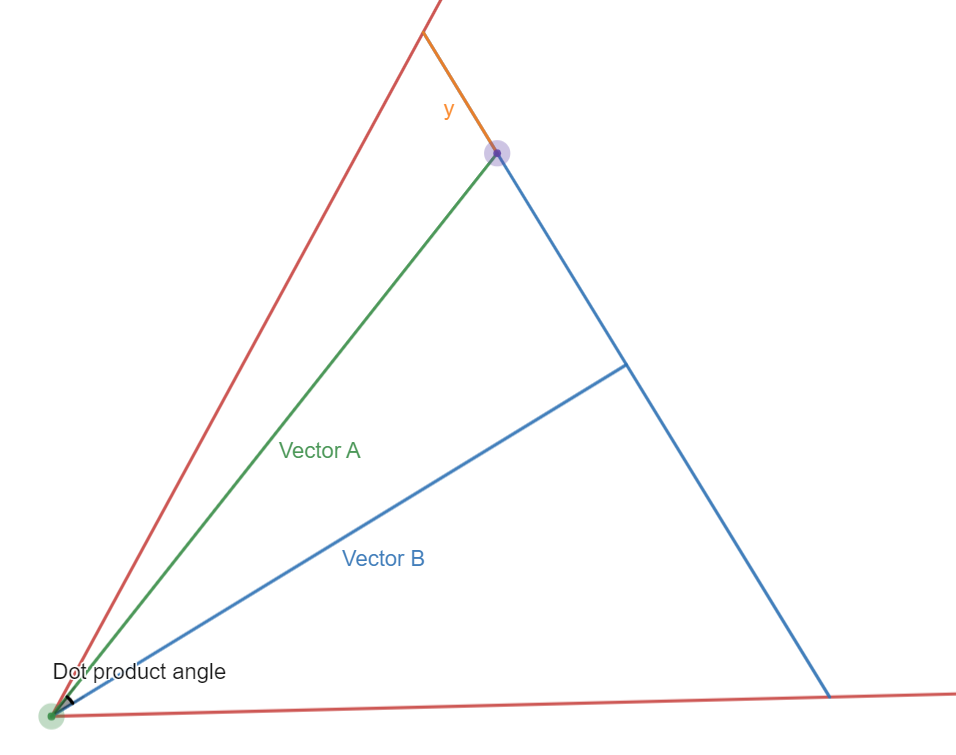
Note: I will be referring to the perpendicular bisector that goes through the entity and is perpendicular to the player view line as line C.
The second part of this problem involves basic y=mx+c line solving in order to figure out if the entity is on the right or left side of the screen, it helps to keep the diagram open for the explanation.This problem is actually just checking if the entity is on the left or right of the player view line.
First we find both gradients, one for the player view line and one for line C. Once we have both these gradients we can find the y intercept for the lines using both coordinates that we have. We do this by reversing y=mx+c into c=y-mx and inputting the respective values of y,m and x. Once we have the equation for both of the lines, we can figure out where they cross and hence the point in the centre of the view frustum that lies on the same line as the entity. We do this by setting each equation equal to each other and rearranging to solve for x. If we do this we can see that the X position of the crossing point is (playerc - entityc)/(playerGrad -entityGrad). Once we have the X position of the crossing point we can put this back into either equation and get the Y crossing point.
For the next part it is important to say what we know. We know the point where line C and the player view line cross, and we also know where the entity position is. With these 2 coordinates we perform a matrix transformation, more specifically the 2x2 rotation matrix. The value we rotate by is the player angle. This means that the crossing point coordinate will lie directly on the line x=0. This means we can check if the new rotated X coordinate of the entity is greater than or less than the crossing point. This will tell us if it’s on the left or right side of the player and hence if it's on the left or right side of the screen.
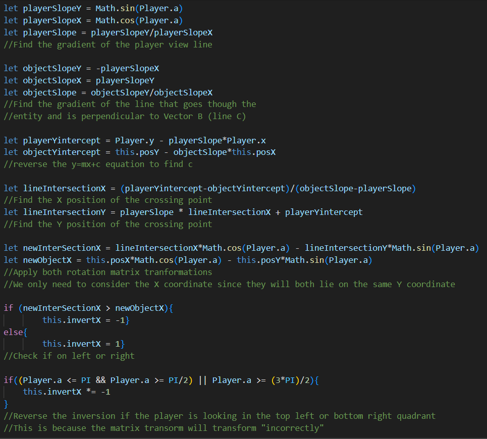
Once we have the entity position on screen, drawing it is very simple. Because we already know how to scale a wall based on a distance, we can scale the sprite in the same way based on its distance to the player. Once we do that we can successfully send the sprite to the draw list.
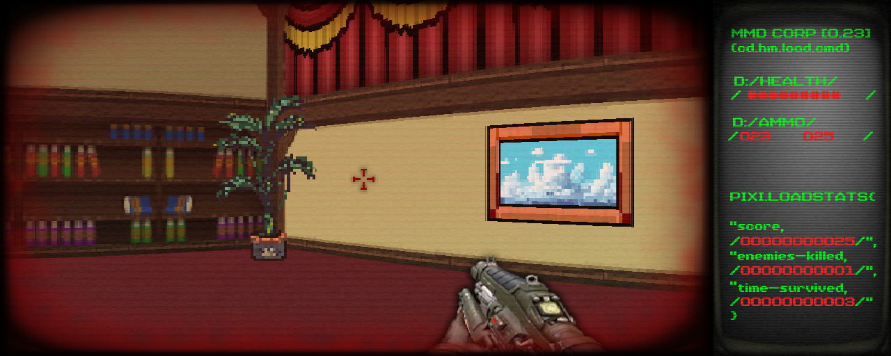
This is what it looks like in game
Checking if the player has hit an entity or vice versa
For an enemy to shoot a player, the only requirement is that the enemy be visible to the player and the enemy be in the attacking state. The shootPlayer method will only be called if the checkOnScreen method returns true.
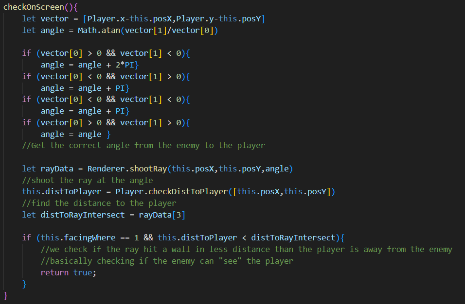
This method will return true if a raycast sent from the enemy collides with a wall after it reaches the player. Meaning the enemy can “see” the player and the player isn’t occluded by a wall.
If this method is true then the shootPlayer method is called.
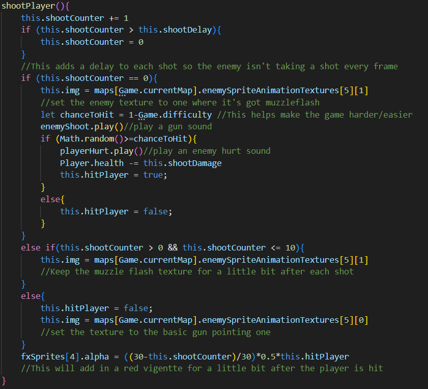
The shoot counter will count up to the shoot delay value, once it reaches that value the shoot counter will be set to 0. The enemy can only take a shot when the shoot counter is 0. This adds a delay to each shot the enemy takes. If a random number ends up being bigger than the one minus the difficulty value then the player will be hit. If the player is hit then the opacity of a red vignette will be set to higher and will slowly count down until the shootCounter reaches 0. There is a bug with that last line where the red vignette stays at full opacity and doesn’t dim down. I haven’t had time to fix it but if I get a chance in the future I will. I suspect the bug is because multiple enemies can shoot the player at once and all enemies can set and change the single alpha value of the texture.
For the player shooting the enemy, a similar process occurs. It should be noted that each enemy themselves checks if they have been shot. This is much more simple than trying to identify which enemy has been shot when the player shoots.
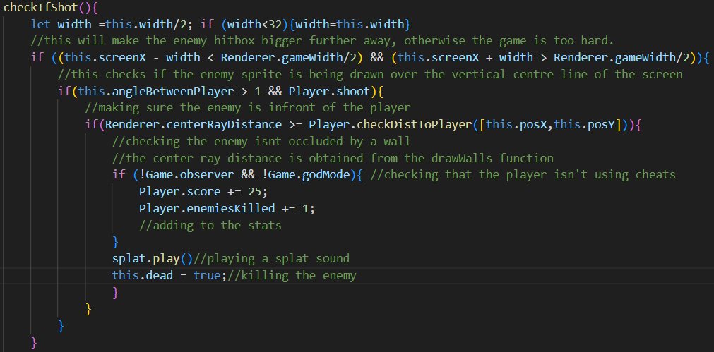
First we make the enemy hitbox bigger when it’s far away to make the game not too hard. Then we check if the X coordinate that we draw the enemy at is crossing over the vertical centre of the line, meaning the player’s crosshair is on the enemy. Then we check if the player is actually facing the enemy (rather than the enemy being 180 degrees behind the player). Finally we check that there are no walls in the way. Instead of shooting a whole new ray for shot checking. I can just check the middle ray that was shot in the drawWalls function and get the distance.
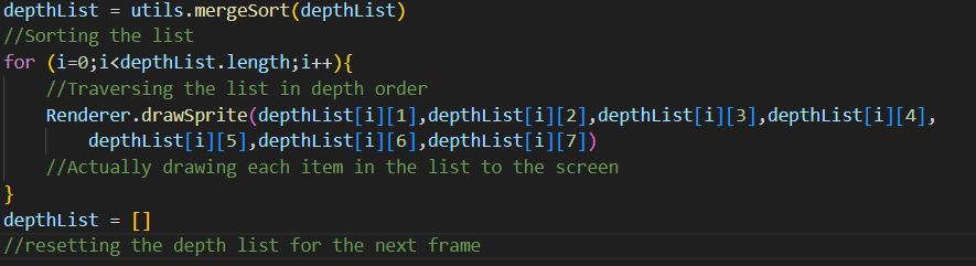
Depth List
This is a global variable that, each frame, will be filled with individual lists with data about drawing each sprite. Each individual list contains the information needed to draw the sprite, e.g. x position, y position, size, tint etc. However it also contains the distance in world space of that sprite. So when a sprite is added to the depth list it is not drawn yet. Only once the depth list has been completely filled will the drawing commence. Before the list is traversed and each sprite drawn the list will be sorted. I used a merge sort in this case because it is a fast sort I am most familiar with. The importance of the depth list is to make sure all the sprites will be displayed in the correct order so it won’t look like some entities are on a layer in front of a wall.
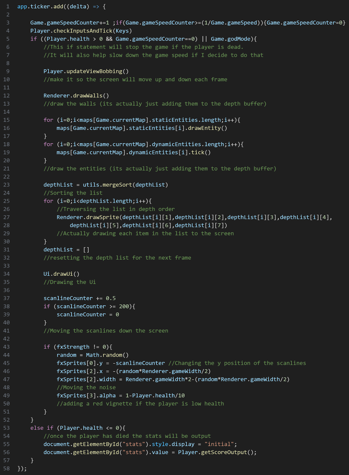
This code is in the main game loop and will happen every frame.
Main game loop
This code is executed every frame and ties the game together and actually makes it work. I won’t explain what each thing is because they aren’t cohesive.
Strong adventurer, you have travelled far...
Yet you still have a long way to go...
There is no treasure at the end of this long ardious journey, you will see nothing but void along the way
Do you still wish to travel further?
Heed this warning, if you travel any further you will delve into madness...
No person has returned from where you are about to venture...
This is a final warning.
Turn back now or face the consequences.
I was lying about the last warning...
THIS is the final warning.
Get dunked on loser

You're still scrolling?
Get dunked on again, double loser
Just letting you know, there really is nothing after this...
Dunked on THREE TIMES...
Bye! MEGA loser